DJI TERRA workflow- LIDAR point cloud processing
Author: Rohith Maben - Last update: 2023-08-31
Citation:
Maben, R. P. (2024). DJI TERRA workflow- LiDAR point cloud processing. Zenodo. doi.org/10.5281/zenodo.11609691
DJI Terra is a computer software for flight planning, and post-processing aerial acquired data. It can control a DJI UAS to fly along a planned 2D or 3D route and provides functions such as 2D map reconstruction, 3D model reconstruction, field planning, and more. DJI Terra has four versions: Agriculture, Pro, Electricity, and Cluster. The point cloud data captured by the Zenmuse L1 is used to obtain a high-precision true-color point cloud. After the point cloud has been reconstructed, users can add annotations and perform a variety of measurements.
1. Similar to 2D and 3D reconstructions, users can create a new LiDAR Point Cloud Processing mission by creating a new mission or importing a mission. Refer to the size of the raw point cloud data corresponding to the following computer configurations to ensure an adequate amount of raw LiDAR point cloud data and that the point cloud data can be processed smoothly.
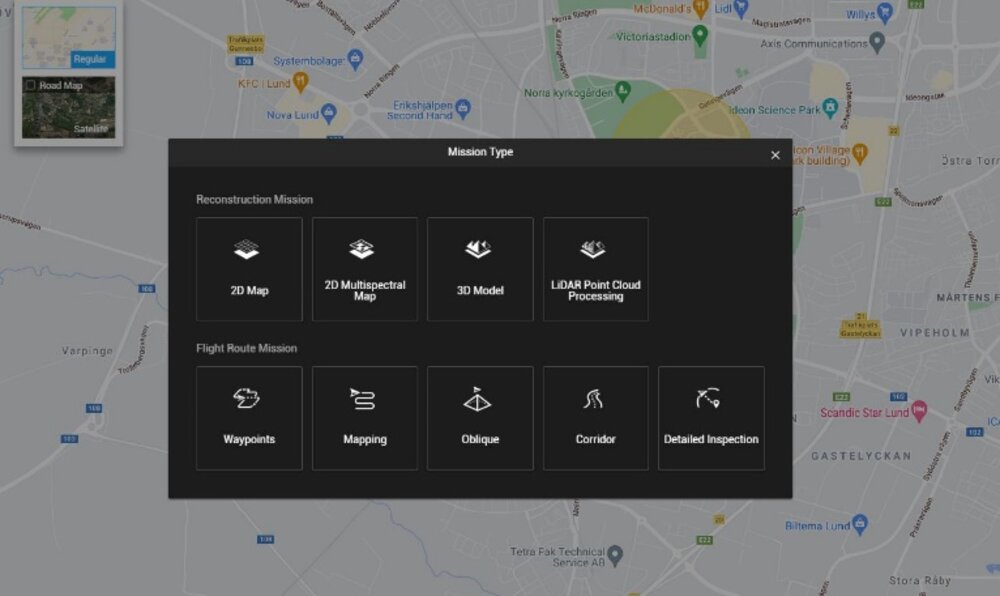
2. Select the folder with the corresponding date to add the LiDAR point cloud data to DJI Terra. The folder must contain the CLC, CLI, CMI, IMU, LDR, RTB, RTK, RTL, and RTS files. The data recorded by the sensor is stored in a folder named in the format: DJI-Year-Month-Date-Hour-Minute, followed by an underscore, Sequence Number, and Custom Name.

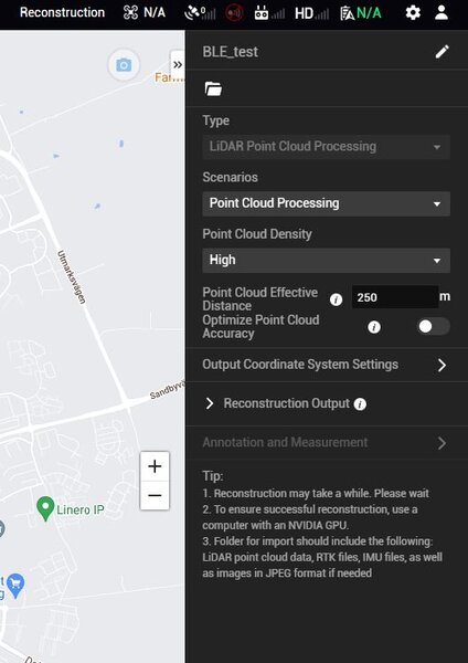
3. Select the point cloud density: high density refers to the original sampling rate, which uses 100% of the point cloud data for processing. The processing results will be of the highest quality but will take the most extended time. Medium density uses 25% of the point cloud data for processing. The processing results will be of medium quality and take much time. Low density uses 6.25% of the point cloud data for processing. The processing result will be lower quality but will take the shortest time to process.
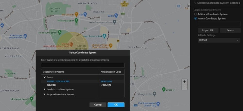
4. Set the output coordinate system: same as 2D and 3D reconstructions. Users can set the output coordinate system so that the results will be converted to the corresponding coordinate system.
5. The software provides the user with certain parameters that can be changed before a reconstruction. Optimize Point Cloud Accuracy: if enabled, the software will optimize point cloud data collected at different times during processing for higher overall consistency and accuracy. Point Cloud Effective Distance: set the distance between the LiDAR sensor and point cloud data. Only point cloud data within the effective distance will be used for processing. LiDAR point data beyond the effective distance will be filtered out.
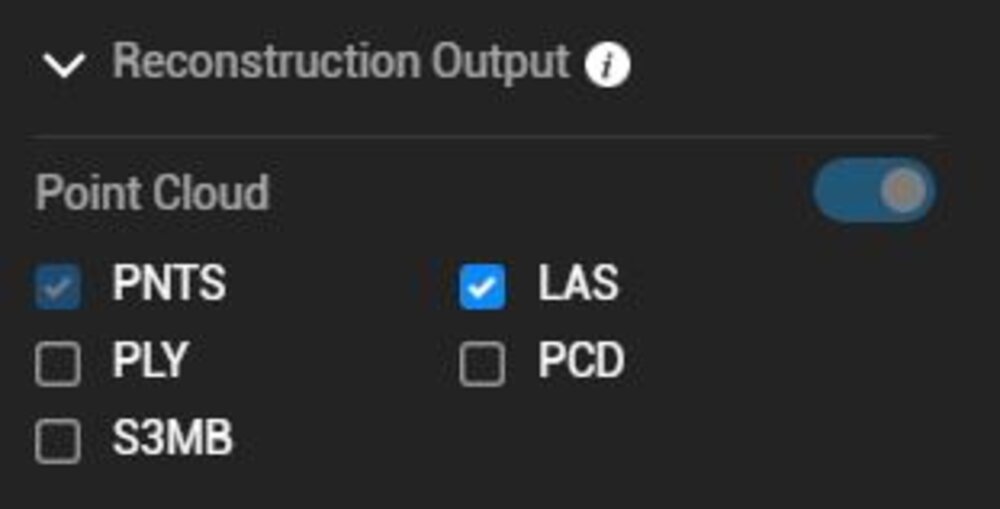
6.Select the reconstruction file formats. If point cloud is enabled, a 3D point cloud will be generated. The default file format for the point cloud is pnts. The point cloud can be set to other formats. LAS refers to the ASPRS LAS format for a 3D point cloud file. PLY refers to the ply format for a non-LOD 3D point cloud file. PCD refers to the pcd format for a non-LOD 3D point cloud file, which is used in Point Cloud Library and can be viewed using Cloud Compare. S3MB refers to the s3mb format for the Super Map LOD 3D point cloud file.
7. Click “Start Processing.” The lower corner progress bar displays the reconstruction progress. Click “Stop” to stop processing and the progress will be saved. If processing is restarted after stopping, DJI Terra will track back slightly from the saved progress before continuing.
8. Multiple processing missions can be started, but only one processing mission can be processed at once. Any remaining processing missions will be queued.
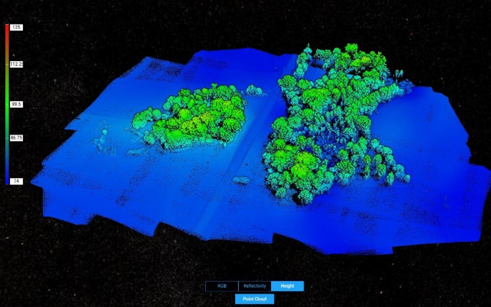
9. After processing, users can translate and rotate the processing results and zoom in or out to view it from different angles. The operations are the same as with 3D models. Select different display styles at the bottom of the screen.
- RGB: displays real color.
- Reflectance: displays corresponding color according to the reflectance of objects with values between 0 and 255. 0 to 150 corresponds to the reflectance within the range of 0 to 100% in the Lambertian reflection model. 151 to 255 corresponds to the reflectance of target objects with retroflection properties.
- Height: displays the corresponding color according to the height of the point cloud.
- Returns: display the corresponding color according to the number of returns when collecting data.
10. Click “Quality Report” to view and save a report in html format. The report includes an overview of the raw data information, software parameters, reconstruction file format, and point cloud processing time.
11. Click on the right of the Annotation and Measurement bar to add annotations and perform a variety of measurements to the point cloud processing results.

