Recording 3D data for monuments or larger volumes: postprocessing
Authors: Stefan Lindgren and Carolina Larsson - Last update: 2023-09-27
Citation:
Lindgren, S. (2024). Recording 3d data for monuments or larger volumes - Postprocessing. Zenodo. doi.org/10.5281/zenodo.13375312
1. Open all the scan files in appropriate software. This is usually the software that comes with the scanner. Either use that software or export the scans to be able to work with them in a different software. *
2. Align the scans so they fit correctly in one common coordinate system and create one single pointscloud. This procedure is also called registration.
3. Remove unnecessary data.
4. Create a mesh from the pointscloud.
5. Add colors to the scan either from the scanner or from photos
6. Create texture if necessary.
7. Export to a useful format.
* most scanner software are proprietary which usually means that what happens inside is not available information. It is a black box. In order to keep the workflow as open as possible, it could be good to choose to work only with open software as far as possible.
How-to introduction
In this how-to a Faro Focus phase shift scanner is used and to get the scans out of the Faro format the Faro software Scene is used. Even though Scene is very specific, the steps taken when using it are very general and would be similar with other scanners and software.
Scene is a useful software, and the alignment procedure is done in Scene, just to show how it can work. But Scene is proprietary and if possible, it is preferred to use open software instead. So, the alignment procedure will be shown in an open software as well. In this case Meshlab is used. The rest of the processing will use Meshlab.
The scans were recorded with big overlap, which is needed for Scene to be able to do the alignment automatically. How-to use Faro Scene for import and alignment
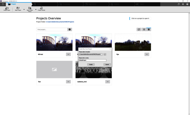
1. Open Scene, create a new project and select where to save it.
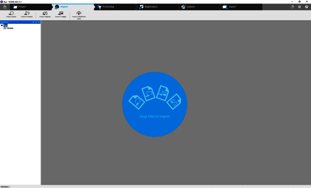
2. Click on the import tab at the top of the Scene window
3. Open the folder with the raw scan files that were saved earlier and drag all .fls files to Scene.
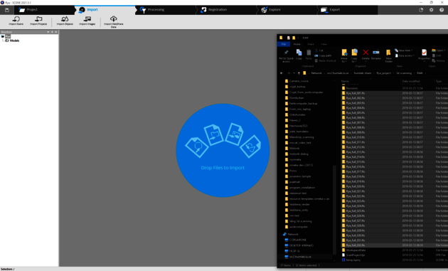
4. Click ok when the files are imported.

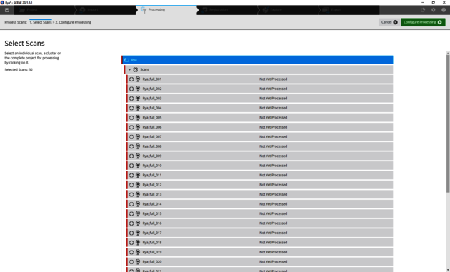
5. Click on the tab Processing at the top of the Scene window
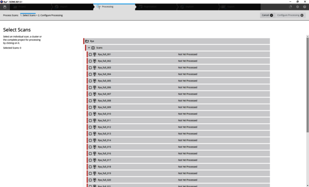
6. Select the top level of the scans to process all scans at once. Click on Configure processing in the right corner of the window
7. The default settings work in most cases.
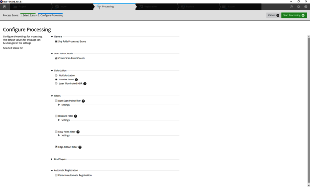
Click on Start processing. What is done when using the default settings is that for each scan, a point cloud is created, the color information from the built-in camera in the scanner is applied and some basic cleaning of erroneous artefacts is done.
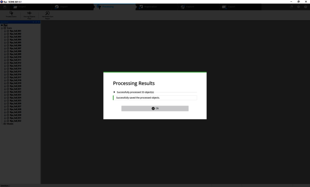
8. When processing is done click on ok
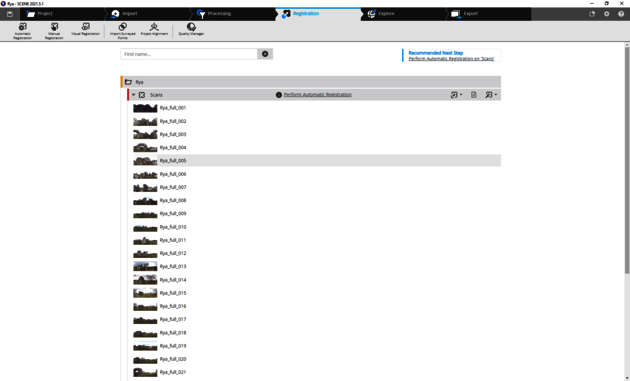
At this point it is possible to continue using Scene to do the registration/alignment. Or export the scans to continue working with the scans in another software. In this example the registration process in Scene will be used, just to show that functionality.
9. Click on Perform Automatic Registration
10. If the scans are made with proper overlap, the default values work fine.
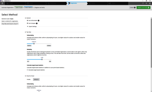
Click on Register and Verify
11. When this procedure is done the scans are shown in 3d and it is possible to check if the registration procedure has produced a good result. If it looks good tick the Yes button under the question Are all scans registered correctly? and click Finish. If the procedure has failed there are possibilities to make adjustments by hand in Scene. However, this is not a Scene tutorial, so the recommendation is to export the scans and do the registration/alignment in another software.
12. To export the scans click on the Export tab at the top of the Scene window.
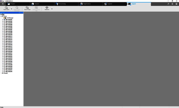
13. To the left in the Export tab there is Export Scans where it is possible to choose between "Export Scan Point Clouds - Unordered" or "Export Scans - Ordered". The Unordered option exports the scans with the center exactly at the position of the scanner in each scan. The ordered option exports the scans with any transformation that has been done in the software. So, if Scene has been used for registration, each scan has been transformed to a position that fits with the rest of the scans. Choose the appropriate option.
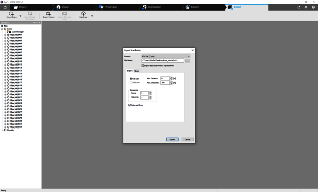
14. Choose a fileformat for the export. Different fileformats have different pros and cons. The .ptx format is an open ascii based format that keeps all information from the scans and can easily be imported in most other 3d software. Select a path and make sure to tic the box “export each scan into a separate file”. Tic the box “Color and Grey.
How-to use Meshlab to check alignment and improve it if necessary
Meshlab will be used to continue the postprocessing. It is an open-source software that can be downloaded from www.meshlab.net
Some basic video tutorials on Meshlab can be found here.
Meshlab video tutorials on 3d-scaning can be found here.
1. A drawback with the .ptx format is that it produces rather big files. A better format to work with is .ply which, as .ptx is an open format. The first step is to open the .ptx files and export them as .ply files. Work through the scans one by one until all of them are in the .ply format. Another possibility is to use the python version of Meshlab (pymeshlab) and use a script that does this automatically (check this tutorial).
2. Import all scans into Meshlab. If there are many scans and the postprocessing computer isn’t able to handle all of them, it might be useful to subsample the scans first (check this tutorial)
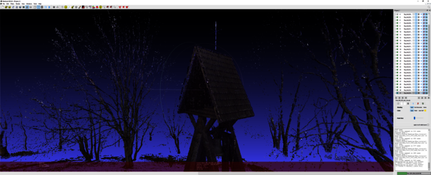
3. If the scans were aligned in Scene, check if the alignment has worked properly. The overlap between the scans should be as close as possible.
4. Small alignment errors like in this example, can be fixed easily.
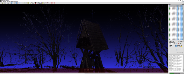
One scan of the clocktower is slightly misaligned, which is obvious when the misaligned scan is removed.
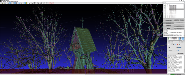
Use the alignment tool in Meshlab. Make sure all layers are visible. Press the yellow A-symbol on the top of Meshlab. In the windows that opens, click “Glue Here Visible Meshes”. Then click “Set ICP params for m” and then click “Process”. NOTICE This method works only when the scans are “almost” aligned. If the difference is bigger the scans need to be aligned by hand first.
5. Save everything as a Meshlab project. A Meshlab project file is a textfile that contains the path to the scanfiles and its transformation matrix for each scan file. One big advantage of this is that the textfile can be edited in a texteditor. If the alignment has been done with subsampled files, they can be replaced with the full files to get all recorded data into the project, just by changing the filename in the textfile.
It might be necessary to click “Process” more than once to get a good result. But make sure to save the Meshlabproject between each processing.
If the alignment errors are bigger or if the scans weren’t aligned in Scene, then the alignmenttool in Meshlab can be used to align the scans by hand. See specific tutorial for that here.
How-to remove unnecessary data from the scans
Cleaning the scans Meshlab has some easy-to-use selection tools and filters to use for cleaning the models.
1. Work with the full scans (not the subsampled) and with one scan at a time. Ctrl-click on the eye in the layer window to open only that scan.
2. Use the selection tools to select the data that isn’t interesting and click on the Delete Selected Vertices button to remove them.
3. Export the cleaned scan and give it a different name. For example, add “_cleaned” to the original name.
4. Continue through all scans and clean out unnecessary data and export each scan until all scans are cleaned.
How-to create a Mesh from the pointcloud
1. Make sure all layers are visible.
2. Right click on any scan in the layer window and select “Flatten Visible Layers”
3. Tick all the boxes in the “Flatten Visible Layers” window and click on Apply. This creates one new pointcloud and removes the individual scans.
4. Export this pointcloud as a .ply file, just to make sure to have it.
This is the result from the case study. Looking at it from the top...
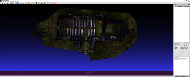
...it is clear that there is data missing. This is due to the fact that all the scans were made from the ground. If that isn’t important, continue with the next step to create a mesh.
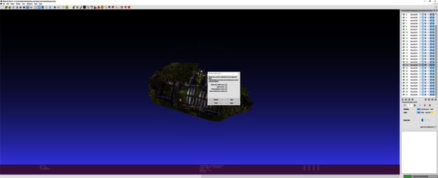
5. Click on the Filters menu in Meshlab. Select “Remeshing, Simplification and Reconstruction” and select “Surface Reconstruction:Screened Poisson”
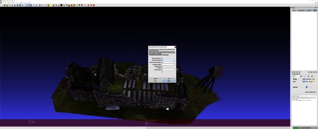
In the “Surface Reconstruction:Screened Poisson” window “Reconstruction Depth” to 11 and press Apply. This step might take time depending on how powerful a computer is being used. The details of the filter can be found in the help section in the filter. But here is a short explanation:
The values to play with are Reconstruction Depth and Interpolation Weight. The Reconstruction Depth sets the final resolution of the model. The default value of 8 gives a fast result but very low resolution. It is worth trying to run the filter with different values for Reconstruction Depth. The higher the value, the longer it will take to process, but the better the result will be. However, trying a value higher than 14 will be problematic for most computers.
The Interpolation Weight is a value to set the crispness of the model in terms of sharp edges and corners. The lower the value the more rounded it will be. Setting 0 will give the original poisson reconstruction. The default value is 4 which is a good startingpoint, but it can result in a noisier model than using the original poisson filter.
The recommendation is to try different values and save the resulting files including the values of Reconstruction Depth and Interpolation Weight in the file name. For example, Rya_model_poisson_12_0 to indicate that the poisson filter was run with 12 for reconstruction depth and 0 for interpolation weight.
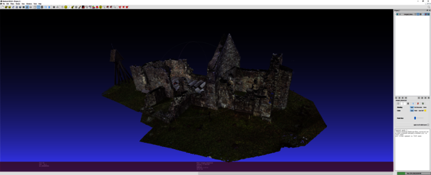
6. Check the result and clean away any unnecessary data.
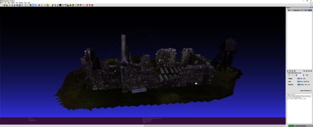
Notice the blobs on the top where data was missing. The reconstruction filter tries to create a mesh based on the pointcloud. When data is missing, it results in those kinds of blobs. They can be cleaned away with the selection tools or cleaning filters.
This is now a complete model with colorinformation from the scanner. In Meshlab it is possible to create texture from this colorinformation.
But to deal with the problems of the missing parts and getting better colorinformation, it is possible to combine the scans with data from photos. This is covered in the next part of the documentation: Recording 3d data for monuments or larger volumes: postprocessing photo.