Vector drawing on 3D surface boundary models polylines and polygons
Vector drawing on 3D surface/boundary models: polylines and polygons
Author: Giacomo Landeschi - Last update: 2023-08-31
Citation:
Landeschi, G. (2024). Vector drawing on 3D surface models in GIS. Zenodo. doi.org/10.5281/zenodo.13372224
Short introduction
The tutorial introduces users to the editing tools available in some GIS software packages to draw vector lines and polygons whose vertices are snapped onto a reference surface of a 3D boundary/surface (B/S) model. 3D GIS can be used to make 3D shapefiles that can help archaeologists or surveyors to keep track of any geometrical discontinuity visible on the 3D model. The typical situation is a stratigraphic excavation where a 3D model of the trench is examined, and 3D drawing tools are used to mark all the different context boundaries visible on the model itself. But this workflow is not limited to it and can be applied and extended to any 3D graphic documentation (architectural survey, landscape analysis, artefact drawing etc.)
Explanation
3D data representation is an important component of the process of documentation of the archaeological record. There are multiple contexts in which archaeologists are expected to produce graphic documentation to keep track of their observations in the field and use the collected data to make interpretations and generate new knowledge about the context under investigation. Regarding 3D B/S models, archaeologists need to take advantage of 3D-enabled tools for drawing using the surfaces of the 3D models as a geometrical reference for defining the boundaries of the observed features. Such boundaries typically correspond to the boundaries of a stratigraphic context or the boundaries of an architectural element that need to be highlighted.
Tutorial
The digitization procedure generally follows the following steps:
- Have the reference 3D boundary/surface model correctly georeferenced and ready in the GIS project.
- Create a 3D line/polygon shapefile (ensure the Z is enabled).
- Start editing the newly created object, filling in the related attribute table descriptive info.
- Stop and save editing.
How-To
This part contains more detailed instructions on each of the steps described in the tutorial.
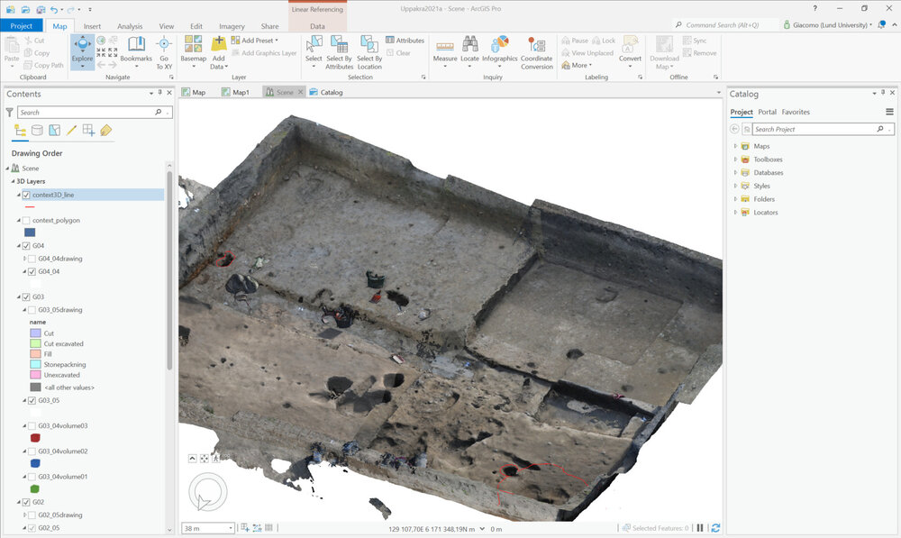
- After the 3D B/S model has been georeferenced in GIS (see tutorial n), it can be opened and added to the current GIS project and visualized in the 3D canvas. The 3D model is typically stored in a geodatabase, where all the texture-related information is kept and can be correctly visualized in the 3D view canvas.
- Going back to the same geodatabase, a shapefile must be created either as a polyline or a polygon making sure to enable the Z value.
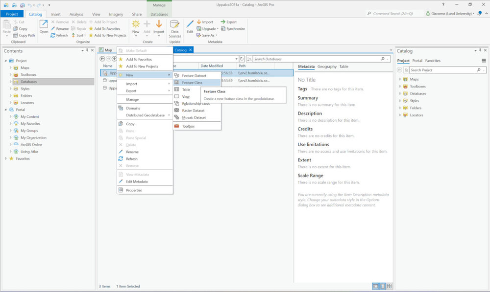
3 Once the shapefile is added to the project canvas (3D ‘scene’), the digitisation is started by enabling the editing function (Analysis – edit).
4. Once the editing is enabled, the shapefile can be edited, and its boundaries can be traced following the 3D model surface polygons as a geometrical reference.
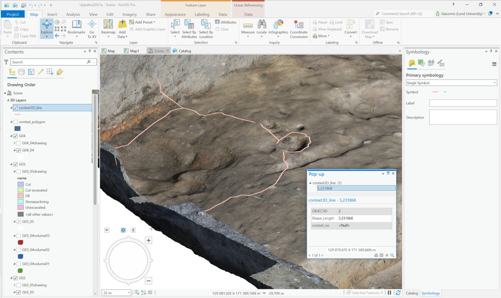
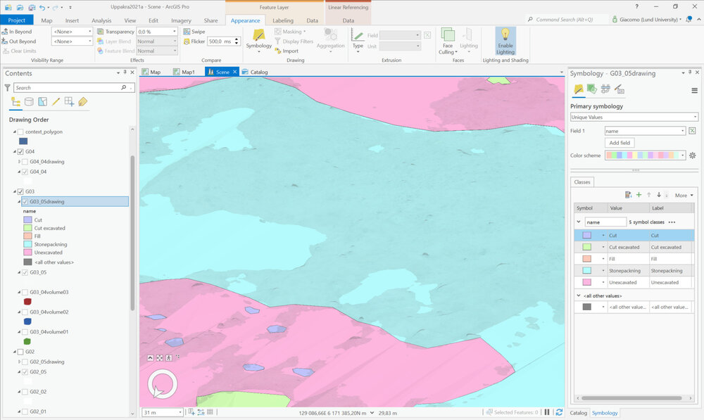
5. Each new polyline or polygon is automatically associated with a new database entry through its attribute table. Here, the user can provide more descriptive information about the digitised object's characteristics by adding new fields and/or filling in the existing ones.

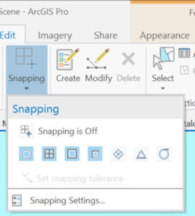
6. To preserve correct topological editing, where no gaps nor overlaps between digitised features occur, it is important to enabling the snapping functionalities.
7. As a last step of the digitization process, edit must be saved and stopped. Polyline/polygon shapefiles are now saved with the last-modified geometry in place.
Reference
The methodology described is developed by using ESRI ArcGIS Desktop/PRO. Other GIS software packages, such as Intrasis enable similar functionalities. An essential prerequisite for these functions is to enable shapefiles with Z enabled, meaning that each vertex is defined by independent x,y,z, coordinates in the Cartesian space. The following video tutorials provide an overview of the polyline and polygon shapefile created to represent excavation units. Digitization process is shown together with the activated snapping options enabling users to draw polylines and polygons correctly: