Georeferencing a 3D model in GIS roto-translation
Author: Giacomo Landeschi - Last update: 2023-08-31
Short introduction
Among the possible georeferencing methods, roto-translation can be applied when users deal with a 3D B/S model that has not been previously georeferenced and, for that reason, needs to be located in the right spatial location. A typical situation is when the 3D model has been generated through the use of a laser scanner, and the obtained 3D mesh is placed in an x,y, and z Cartesian space defined by a local coordinate system.
Explanation
Despite increasing software packages being implemented with tools enabling users to georeference the 3D mesh (CloudCompare, Meshlab), dealing with geographic coordinates is still a tricky task for most 3D modelling software. This is why it is sometimes necessary to georeference a 3D model directly in GIS by using some editing tools that enable users to move and rotate the vector objects along the Cartesian axes. In addition, many archaeological objects, such as single monuments, buildings, and caves, require users to use a laser scanner for their acquisition. This is when roto-translation is a good option for placing these objects in their actual geographic location coordinates.
Tutorial
At least 4 main steps define the workflow to enable users to georeference a 3D model using roto-translation tools.
- Setting up a reference layer to adjust the location of the imported 3D model.
- Importing the 3D model, making sure it is correctly scaled.
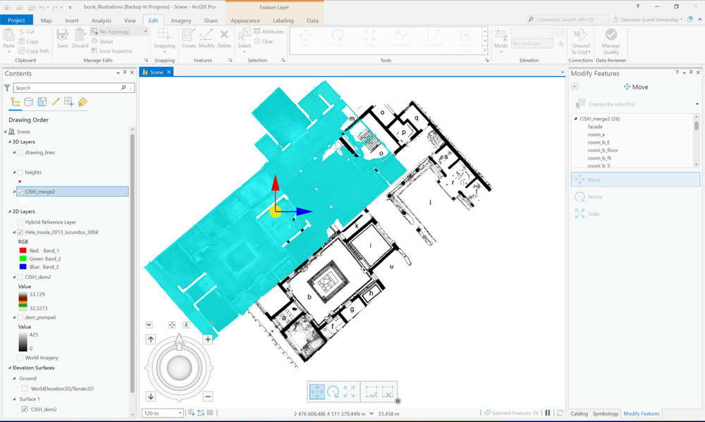
- Editing the 3D model to move it to its right location based on the reference layer defined in step 1.
How-To
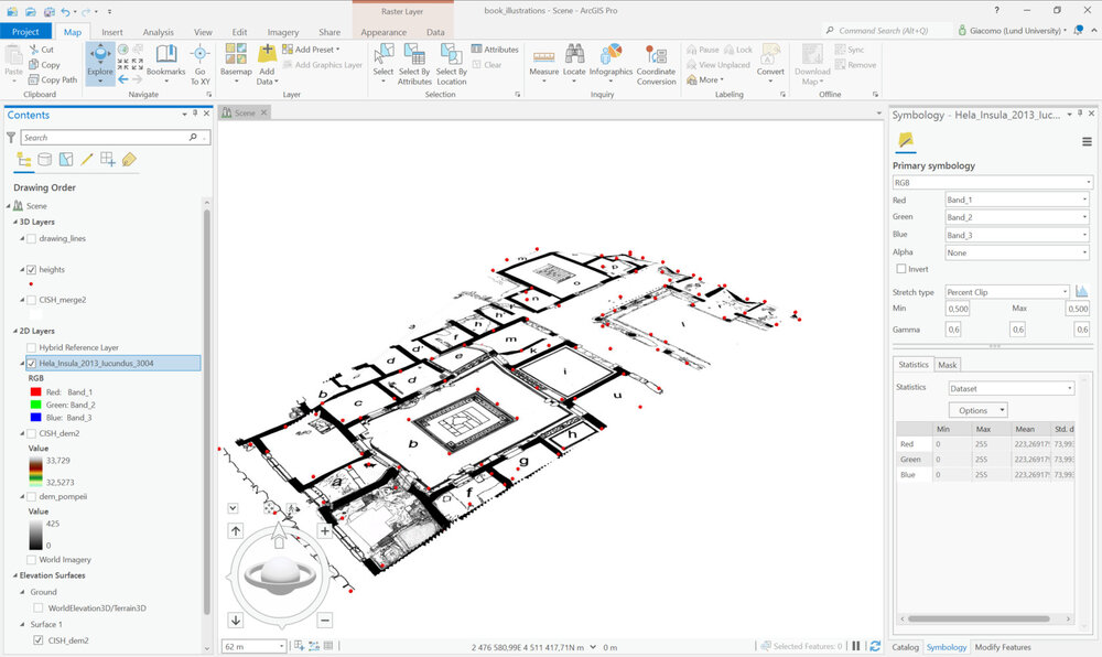
As a first step, users need to define the reference layer to be used for placing the 3D model in the right location based on a pre-defined (or customized) geographic coordinate system. Typically, a combination of cartographic sources and an accurate Digital Terrain Model (DTM) are needed to provide respectively x,y and z information to be used as a reference source. In this example, a reference raster map of a portion of a Pompeain neighbourhood is used to georeference a 3D model of a single Pompeian house acquired with a terrestrial laser scanner and post-processed in Meshlab.
The plan of the Pompeian house provides the x and y coordinate information to move the model to the right position along these two axes.
Additional information is needed to place the model in the correct position along the Z axis. To this purpose, a DTM is generated from a set of height points previously acquired with a total station during the field survey.
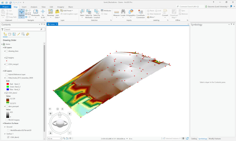
Once the DTM is ready, the raster map is draped onto it to make it easier for the user to complete the roto-translating operations and move the 3D model of the house to the right position in the geographic space.
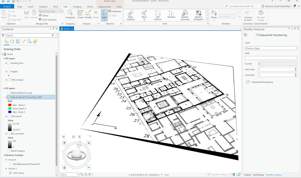
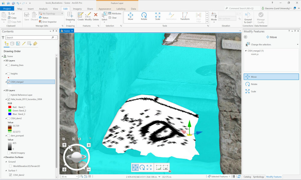
The 3D model (here is the Pompeian building) is imported as a multipatch feature class from the project geodatabase, where it is stored. Then in editing mode, its location is adjusted with the ‘move’ function.
Reference
ArcGIS Desktop/PRO was used to carry on the described workflow. As a rule, to perform these tasks, it is essential to use GIS software capable of handling 3D B/S models as well as 3D coordinate-enabled shapefiles (with Z coordinate).
To georeferenced 3D models, users must have a reference layer that provides x,y, and z geographic coordinates. Cartographic sources, as well as satellite images, represent typical datasets that are sued for this purpose. Information typically comes both in raster and vector format.