Recording 3d data for monuments or larger volumes: postprocessing photo
Authors: Stefan Lindgren and Carolina Larsson - Last update: 2023-11-21
Introduction
In many 3d-documentation cases it is a good idea to combine scanning with photo documentation. Color aquisition could be better from photos, so making a texture from photos and geometry from 3d-scanner will give a very good total result. Another case could be if scanning was done from the ground and top part of the object wasn’t recorded, then a photographic campaign from a drone could solve that problem.
In these type of cases it will be necessary to align the results from the scanner with the results from photos. This tutorial shows one way to do this, using scans and photos without ground control points from gps.
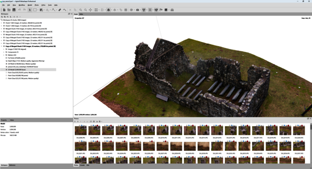
Starting point is a Metashape project and a scanning of the same object.
Workflow
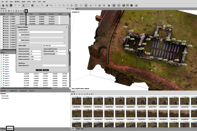
1 Open the Metashape project and make sure that it is set on local coordinate system. Then add markers to features that are clearly visible in the Metashape project as well as the scan.
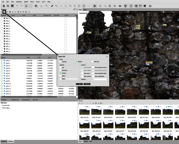
2 To export the markers, click the Export Reference button in the Reference header and save it as a text file. Make sure to select Markers and choose comma as delimeter.
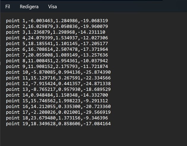
4 Open the text file in a simple text editor and remove the header so only the label and the x, y and z coordinates remain.
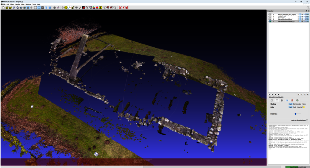
6 Open Meshlab and import the scan of the same object as in the Metashape project. This will not be the final model, so you can use a simple un-edited Poisson mesh of the scan data.
7 Activate the georef tool in Meshlab.
8 Click on Load Reference Points From File and select the text file created from the Metashape project.
Now the list of points are shown as reference to the right and there is a possibility to add corresponding point on the scanner mesh on the left side, which is called MOVING in this tool.
9 Exactly the same points that were picked on the Metashape project should be picked here on the scan. First click the Esc button to be able to interact with the mesh. In the list of points click on the point you want to add and the click “Pick current point on MOVING” and double-click on the mesh on the right spot.
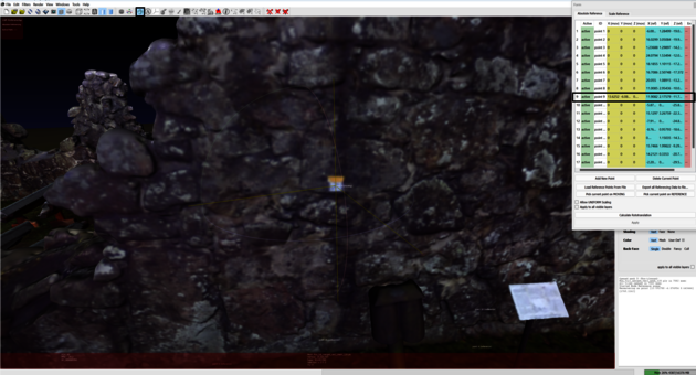
10 Continue to pick all points that was picked in the Metashape project, the same way as described above.
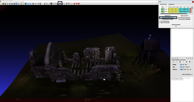
If you would like to move the scan model to the same position as the model in the Metashape project you could click on the Calculate Rototranslation in the georef tool, but in this example we will move the Metashape model to the same position as the scan model using the points we picked.
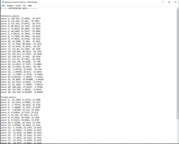
When done placing all the points click on “Export all Referencing Data to file...” button in the georef tool and select a name and place to save that file.
11 Open the file in a texteditor. It looks something like this.
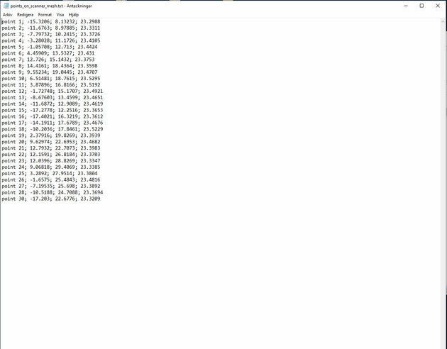
12 Delete everything except the picked points and save the file. The file should have this structure.
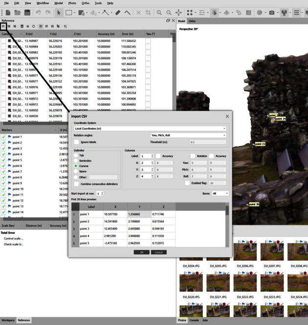
13 Go back to the Metashape project and click on the Import Reference button in the Reference header and select the file just created.
14 Click on Update Transform and make sure that the points in the markers now are the points that was picked from the scanner.

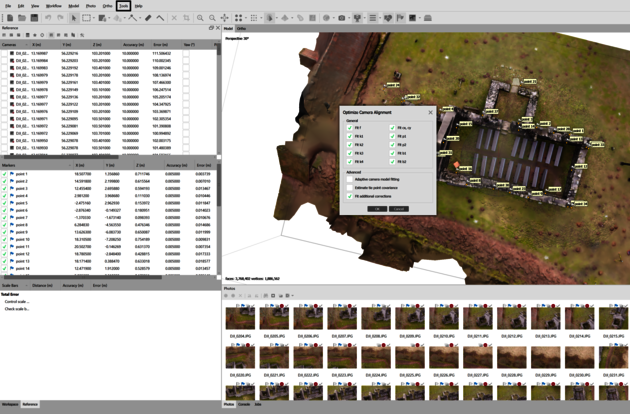
15 Now you can try to improve the model and alignment by optimizing the cameras (Tools>Optimize Cameras). You can also try to improve the model by deleting points with a high reprojection error factor (Model>Gradual Selection) and optimizing the cameras again.
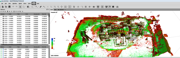
16 If you only want colour information from the Metashape project, continue to step 30, however if you also need geometry from the missing parts in the scans, you could continue with the usual reconstruction steps. In this example a newly densed point cloud was built (Workflow> Build Point Cloud). Check the Calculate Confidence option when building the point cloud to easier clean out bad data (Tools>Point Cloud>Filter by Confidence) before exporting.
17 Export the point cloud as a .ply file.
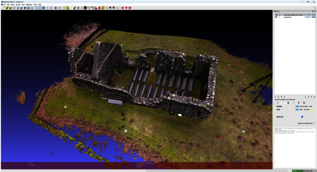
18 Import it in Meshlab.
You can either use the polygon tool to manually select the parts that are missing in the scan data and move it to a new layer and save it, but in the following steps we’ll look at a way to semi-automate the selection.
19 A decimated point cloud of the merged scans is imported in the same Meshlab project as the Metashape point cloud.
20 Select all the points in the merged scans point cloud (Filters>Selection>Select All).
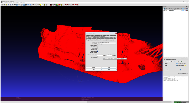
21 Transfer the selection from the merged scans point cloud to the Metashape point cloud with the Vertex Attribute Transfer filter (Filter> Sampling> Vertex Attribute Transfer). Set the merged scans point cloud as source and the Metashape point cloud as target. Check the Transfer Selection option. Change the distance search to something smaller, e.g 5 cm.
22 Invert the selection on the Metashape point cloud (Filters>Selection>Invert Selection).
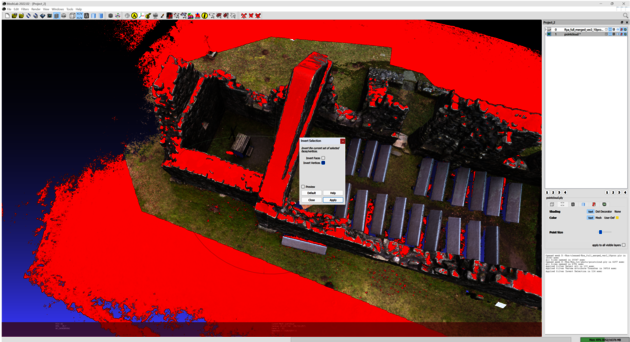
23 We’ll have to do expand the selection in the Metashape point cloud to select the points closest to the scan data (since the first Vertex Selection Transfer selected 5 cm outside the scan boundary).
You can do this by moving the selected vertices in the Metashape pointcloud to another layer without deleting the original (right-click on the Metashape layer and choose Move selected vertices to another layer).

24 In the newly created layer, select all vertices (Filters>Selection>Select All).
25 Do a new Vertex Attribute Transfer with the new layer as the Source and the Metashape point cloud as the target. Check the Transfer Selection option. Set the distance search to 5 cm.
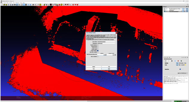
26 Move the now expanded selection in the Metashape point cloud to a new layer and save it.
27 Open the original scan project with all the scanned point clouds and add the point cloud that you just saved.
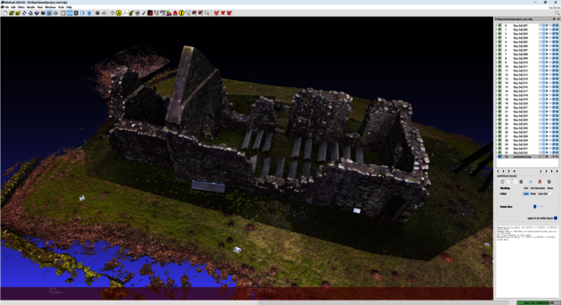
28 Flatten the layers and create a Poisson mesh as in the previous tutorial.
29 Export the model as a .ply file.
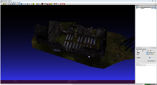
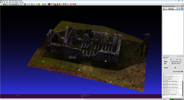
30 Import the model to the Metashape project.
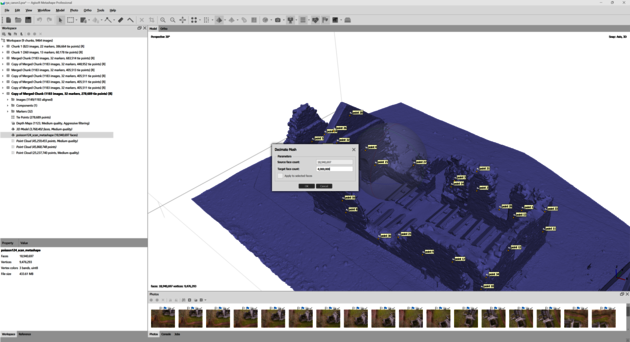
31 If the scanned mesh is very dense, it is a good idea to decimate it (Tools>Mesh>Decimate Mesh). Of course it depends on what it should be used for.
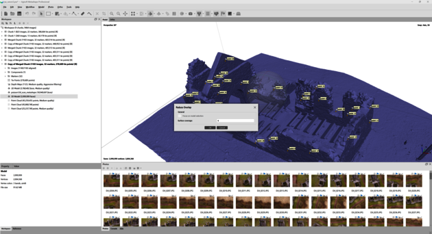
32 If the project contains many photos it could be a good idea to disable some photos. In the Tools menu select “Reduce overlap”, which will disable photos that are not necessary for the texture. Check manually that there are no strange choices. Disable strange photos and enable better.
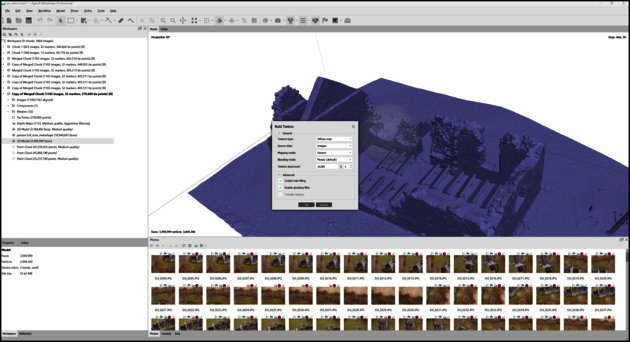
34 The .obj format is good if you want to export a model with a texture.