Generating 3D models from aerial images using the DJI M300+ P1 payload
Author: Rohith Prem Maben - Last Update: 2026-04-27
Prem Maben, R. (2026). Generating 3D models from aerial images using the DJI M300+ P1 payload. Zenodo. doi.org/10.5281/zenodo.19732471
Introduction
In this tutorial, we’ll walk you through creating accurate 3D models using aerial data (images) captured with the DJI Zenmuse P1 camera and processed in RealityCapture. From setting up the DJI P1 sensor on your drone to capture high-quality photogrammetry images, we’ll cover essential flight planning tips to ensure optimal data collection. Then, we’ll look into the post-processing workflow importing the imagery into RealityCapture, aligning images, and generating a detailed 3D model.
Tutorial
Learning outcomes:
- Preflight setup and data capture with DJI M300
- Loading and setting up the images in Reality Capture
- Generating a high resolution 3D model for further analysis.
Supported Hardware: Matrice 300 RTK with Zenmuse P1
Step 1 Preflight setup
Hardware Setup: Ensure the Zenmuse P1 is properly installed on the Matrice 300 RTK. Power on the aircraft and link it with the remote controller.
RTK Configuration:
In DJI Pilot, go to Camera View → RTK Settings.
Select the RTK service type and confirm that the RTK status shows 'FIX' for both positioning and heading.
Safety Settings:
Set Return-to-Home (RTH) altitude, Home Point, and Failsafe behavior based on obstacles.
If flying near a GEO zone, set the flight altitude at least 5m below the zone’s limit.
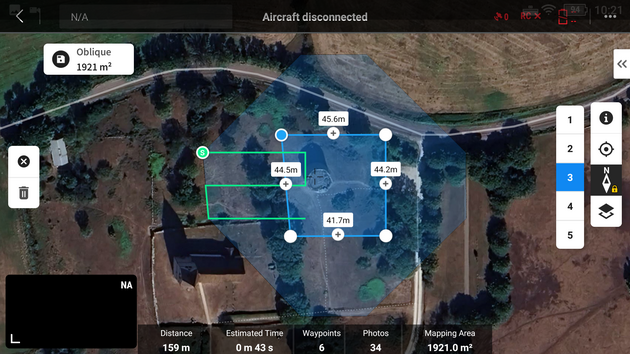
Step 2 Mapping Mission Setup
In the DJI Pilot Application on your hand controller, go to Mission Flight → Create Route → Select Mapping Mission. Adjust the scan area by dragging the map and adding waypoints (tap +).
Smart Oblique enables efficient aerial mapping by automatically generating a flight route that captures orthophotos and oblique photos in a single mission. This feature reduces the photo count and improves post-processing efficiency by capturing only reconstruction-relevant images at the edges of the mapping area. The aircraft adjusts flight speed based on photo requirements (e.g., faster for fewer photos, slower for more). The gimbal pitch and shooting direction (forward, backward, left, right, or orthophoto) vary dynamically. The mapping area, flight height, and gimbal pitch determine the flight area. Changes to these parameters will alter the flight path.
We will be using this feature for our data acquisition. Enable Smart Oblique in the mapping mission settings before flight.
Configure Mission Parameters:
Category | Details |
Camera Settings | Select Zenmuse P1 (35mm) based on your lens. |
Flight Settings | Set altitude, takeoff speed, route speed, and completion action. |
Elevation Optimization | Enable for better terrain adaptation. |
Advanced Settings | Adjust side overlap, forward overlap, course angle, margin, and photo mode. |
Recommended Settings for Orthophoto Missions:
| Maximize route speed for efficiency, use First Waypoint Autofocus, and disable dewarping. |
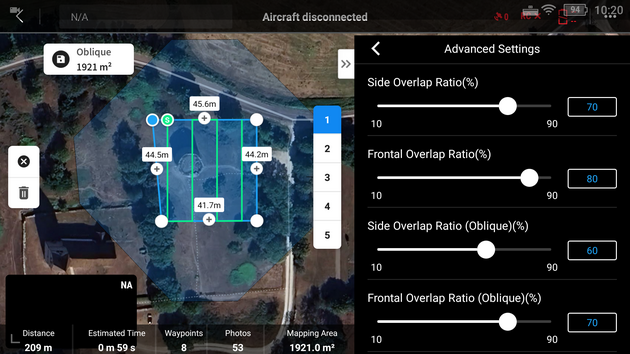
Payload Settings: Set focus mode to First Waypoint Autofocus. And Disable dewarping for orthophoto missions.
Save & Execute: Tap Save Mission, then Upload & Execute.
Post-Flight Steps: Power off the aircraft after completion. Remove the SD card from the P1 and transfer files to a computer for processing.
After completing your Smart Oblique flight with the DJI Matrice 300 RTK + Zenmuse P1, follow these steps to import and process your data in Reality Capture.
Step 3 Setting up the project in Reality Capture
The following tutorial is tested on reality capture version 1.4.2
Transfer Photos
Remove the SD card from the P1 and copy all images to your computer. Ensure photos are in JPEG format (recommended for Smart Oblique).
Launch Reality Capture
Open Reality Capture and create a new project. More information on setting up the software on your workstation can be found here: www.realityscan.com/download
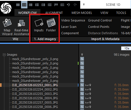
Import and align Images
Under the workflow tab, Go to File → Add Folder (or drag & drop images into the workspace). Reality Capture will automatically detect camera positions if geotags are preserved.
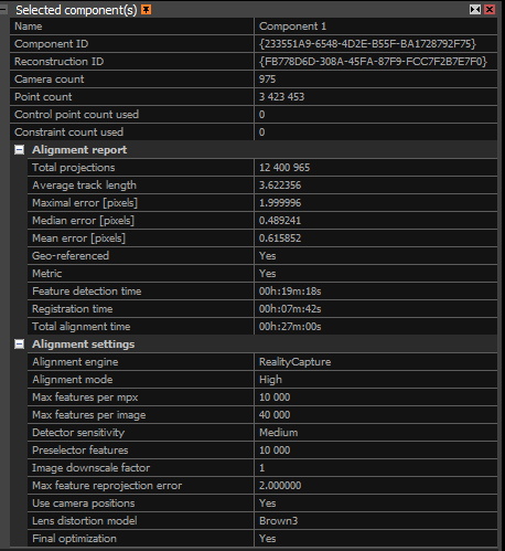
Check Image Alignment: Verify that RTK geotags and gimbal angles (-45° for obliques) are correctly recognized. If needed, manually adjust alignment using Control Points. Under the process subsection in the workflow tab, click on align images. The alignment process in RealityCapture creates a sparse point cloud by identifying and matching key features across your photos. This foundational step determines the accuracy of your entire 3D model. A well-aligned project is essential before moving forward with texturing and export. Start by reviewing the Alignment Report (found under the "Alignment" tab) for these key statistics:
Camera/Point Counts: More aligned cameras and points usually mean better quality.
Under the Alignment on inspect to visualize the alignments and spot issues.
| Metric | Metric |
|---|---|
| Matches | Check if overlapping images connect correctly. |
| Lens Distortion Grid | Ensure grid lines bend naturally (no extreme warping). |
| Inspect Tool | Zoom into the 3D model to spot misalignments |
| Alignment Report Metrics | Total Projections: Total times 3D points appear across images (higher = better overlap). |
| Average Track Length | Average number of images a point appears in (aim for higher values). |
| Errors | Includes Maximal Error (worst-case pixel error) and Median/Mean Error (aim for <0.5 pixels for high accuracy). |
| Geo-referenced/Metric | Confirms whether your model has real-world scale and coordinates. |
| Alignment Time | Indicates the duration of processing. |
The key take away here is that with high point counts and low errors is what we aim to achieve. We can fix issues by adding images, control points, or adjusting settings. Always verify with the Inspect Tool for hands-on quality checks. This helps ensure your model is accurate and ready for texturing and export.
The advanced quality analysis options are used to analyze dependencies among cameras in a scene. In the figure 6, several cameras are marked with the same color due to common virtual components.
1.Camera relations: Component connectivity: This parameter shows minimal connections with neighboring cameras/images. If at least this number of edges are among cameras, then those cameras are connected into one component (cameras marked with the same color). The edges among the cameras are created based on the following settings.
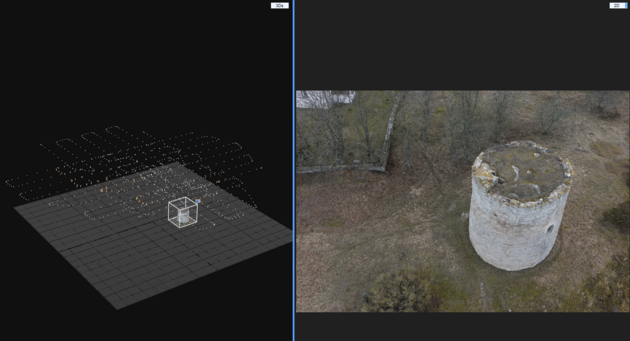
2.Misalignment detection: This tool helps you find problem areas in your scene, like misaligned cameras or points that don't match up well. Once the tool runs, you’ll see colors in the 3D view. Each color group represents a separate problem area, known as a "misaligned component." Misaligned cameras will also appear in random colors and appear larger than the standard input cameras. Use this tool to spot weak areas, then adjust or add control points to improve the alignment and accuracy of your scene.
In this dataset, during the alignment, most of the area around the tower had dry vegetation and trees that were harder to align
3.Point cloud uncertainty: Reality Capture provides two methods to assess the reliability of your point cloud and identify areas that may need additional images for better accuracy. Understanding these methods helps you recognize weak points in your reconstruction before they become problems.
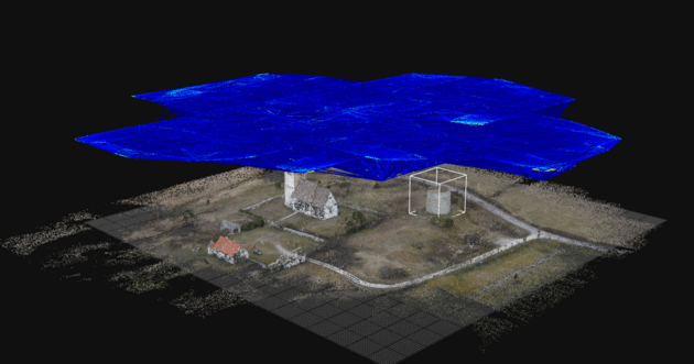
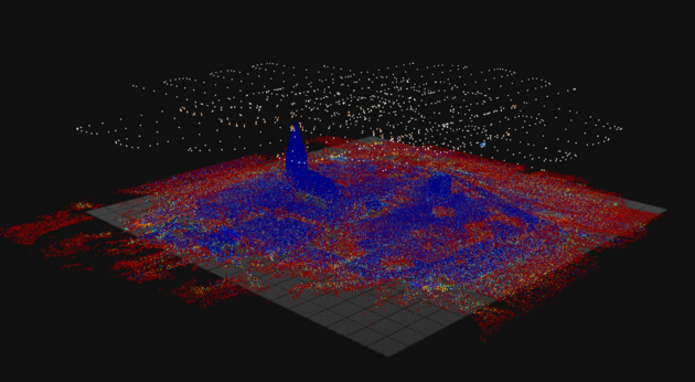
The Relative Method is designed for non-georeferenced models. This approach calculates uncertainty by comparing all tie points against your most stable points (by default, the steadiest 70% of points, displayed in blue). Points outside this stable range are color-coded on a spectrum: blue indicates precise, reliable points, while red indicates areas with lower accuracy that could benefit from improvement. The color gradient helps you quickly spot problem zones. Red areas typically mean those regions were captured from fewer angles or at difficult perspectives. This can be improved by adding more images shot perpendicular to the uncertainty visualization lines.
The Absolute Method is suited for georeferenced models i.e projects where your images have GPS coordinates (the model used in this tutorial) or are aligned to a known coordinate system. Instead of comparing points to a percentage baseline, you set fixed uncertainty thresholds in real-world units (meters, feet, etc.). For example, you might set 0.01 units as your blue threshold (minimal uncertainty) and higher values for yellow and red zones (increasing uncertainty). This gives you control over what precision level you're willing to accept.
Step 4 Mesh generation
Reconstruction region
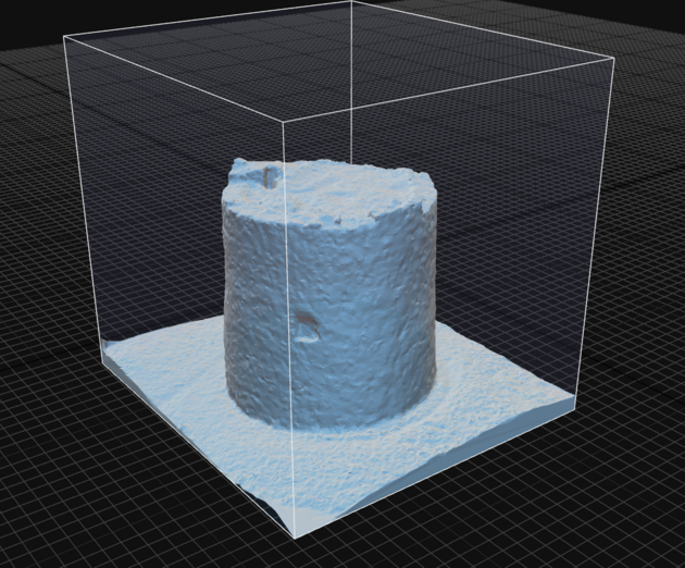
If there is a certain object of interest within the entire dataset that needs to be modelled, the “set reconstruction region” can limit the volume to the specific object and reduce computation time.
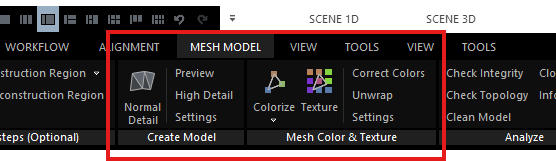
After fixing the alignment issues, we can now proceed to generate a mesh model from the captured images. Under the mesh model tab, select the preview option if you want to quickly create a low detailed 3D model.
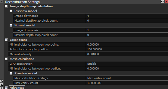
During the reconstruction process, Reality Capture analyzes the images and calculates a depth map for each image. This depth map is a 2D image where each pixel stores information about how far away that part of the scene is from the camera. When the mesh is generated, the following settings can be controlled by the user to control the final quality of the results.
1.1 Image Downscale This setting controls the scaling of images used in depth map computation. The downscale factor affects both speed and detail.
Factor 1: No scaling (100% resolution)
Factor 2: Each side of the image is scaled down to half, resulting in 25% of the original resolution.
Higher Numbers Increase the factor further to reduce detail and enhance computation speed.
1.2 Maximal Depth-Map Pixel Count This setting determines the maximum number of pixels in the depth map. It works alongside the image downscale setting. A default value of 0 means that this setting will be ignored. For effective use, ensure you set a high value.
1.3 Mesh calculation strategy Here you can choose between Sparse point cloud vs. Max vertex count. This setting is primarily based on model resolution and file size restrictions.
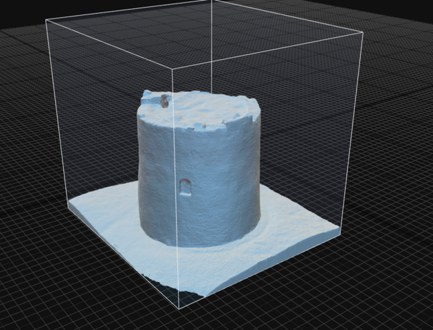

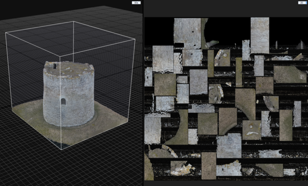
Step 5 Applying textures to the mesh model
In order to apply texture we first unwrap and then click on texture. These options can be found under the Mesh model tab.
The Unwrap Tool handles converting of 3D geometry into a 2D texture space. This panel controls how the software flattens your 3D model for texture application.
The Unwrap parameters section is the most adjustable area. Key settings include texture resolution boundaries (from 512×512 to 8192×8192), which directly impact final texture quality.
The unwrap method (set to Geometric) determines the flattening algorithm, while style controls how texture atlases are organized. The gutter value of 2 prevents texture bleeding at seams.
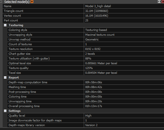
The "Default grouping factor" (currently 1.0) is your primary user input for balancing texture detail vs. computational speed. Lower values (0.5–0.8) preserve more fine detail but increase processing time; higher values (1.2–1.5) speed up processing but may lose subtle surface details.
Step 6: Export the Model
After creating the textured 3D model, you can export it for use in other software or applications. To export the model, go to File → Export and choose the file format you need (e.g., .obj, .fbx, .ply, .stl).
Export the model and share it with others or import it into other 3D modeling or visualization software for further analysis.
References:
DJI P1: enterprise.dji.com/zenmuse-p1
DJI M300: www.dji.com/se/support/product/matrice-300
Model settings : rchelp.capturingreality.com/en-US/appbasics/modelsettings.htm
Alignment settings : rshelp.capturingreality.com/en-US/tools/inspection.htm